Quick Start
Short guide on how to program EVA via drawing to follow 2D tool path. Example use case:
Prerequisites
Download as zip from GitHub. Put in desired location (Desktop, Documents, ect)
Free download on Autodesk site. Sign up for a new account then follow the instructions.
Important, cd into the Drawing Code directory. Now to install, execute the following from your computer’s terminal (mac + linux):
pipenv install git+https://github.com/automata-tech/eva_python_sdk.git@master#egg=automata
Getting Started
1. Take a photo of the desired tool-path. Typically, the further away you are the less perspective distortion there will be. At the same time, make sure the important features of the path are captured with sufficient resolution.

2. Open Fusion 360, Start a new design, import the photo onto the top plane (ensure photo was in landscape otherwise fusion will distort it). Ensure that the axis are pointing in same direction as in the photo. With the current axis orientation, forward, left and right in Fusion corresponds the same directions relative to EVA in real life.
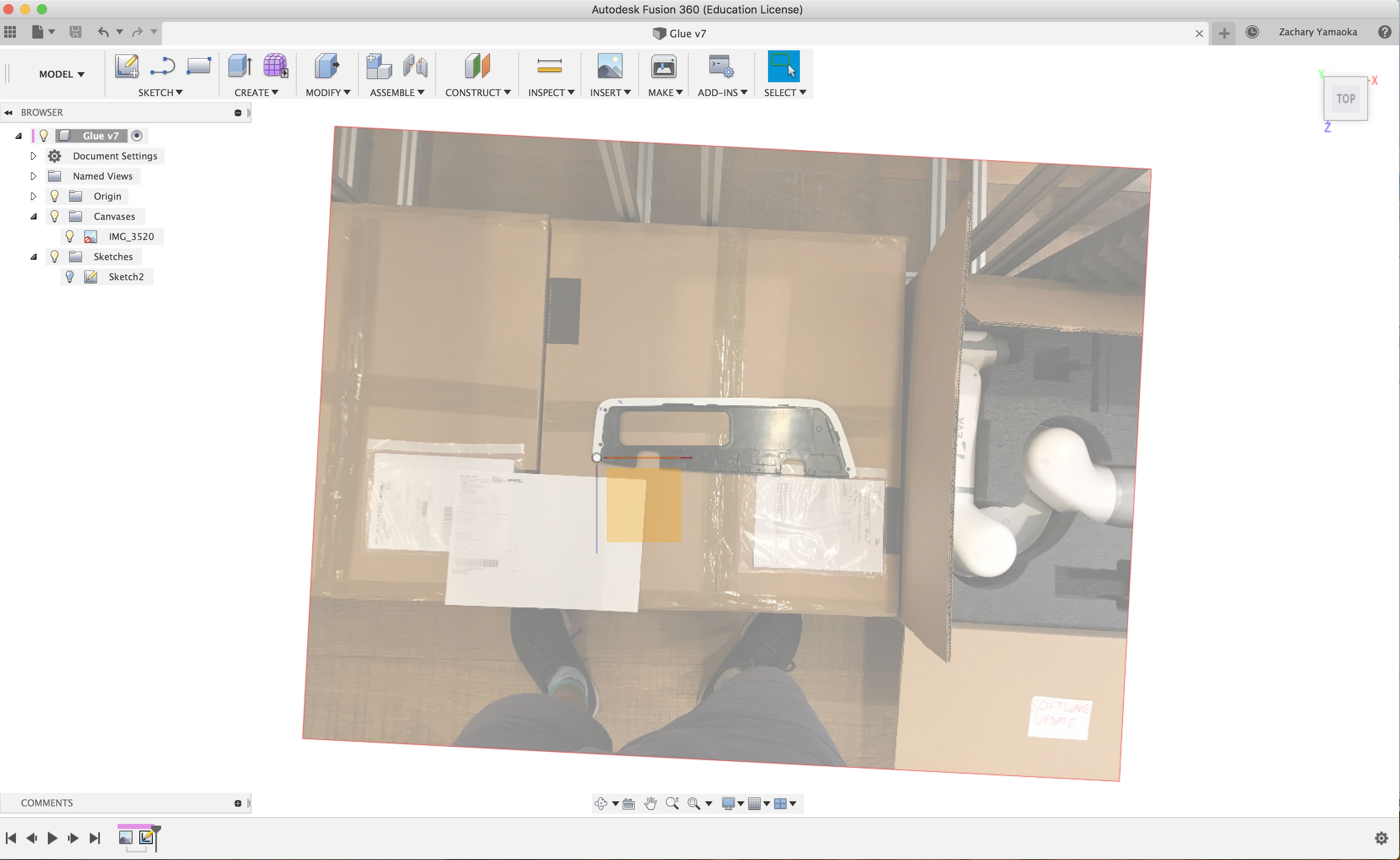
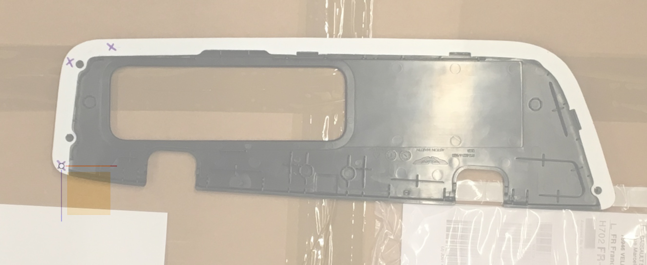
3. Calibrate photo size in fusion and then center the intended starting point on the image at the fusion 360 origin (location where 3 axis intersect).
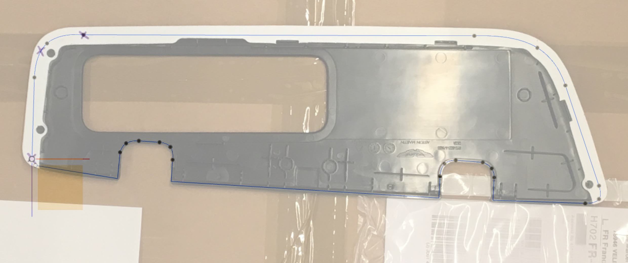
4. All tool paths must start at the origin, and cannot loop back. The path must be constructed using only straight lines and only 3 point fit point spline’s. Ensure there is at most one sketch in the file at any point.
The lines will be converted to linear movement and the splines to pass-through points in choreograph.

5. Next you will have to run the code to export the drawing information. Navigate to the add in button, click on Scripts and Add-Ins.
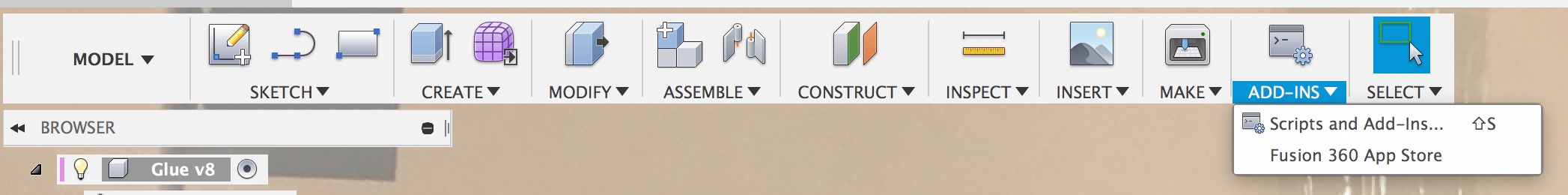
6. Then click the green plus next to My Scripts. Navigate to where you downloaded the Drawing Code, select the Fusion 360 folder, and click open.
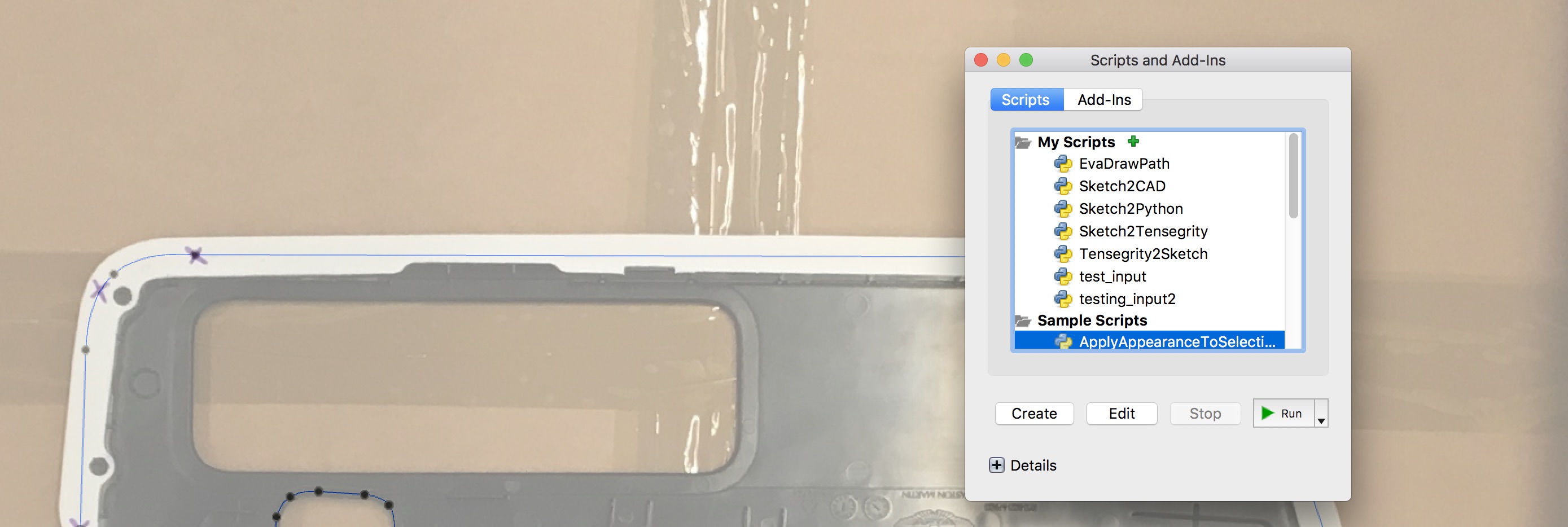
7. Select the script EvaDrawPath and click edit. After a brief loading screen, the spider editor should open

Edit the line:
file_directory = "/Users/zachyamaoka/Documents/Eva_2D_Drawing"
So that it points to the location of the Eva_2D_Drawing directory on your computer
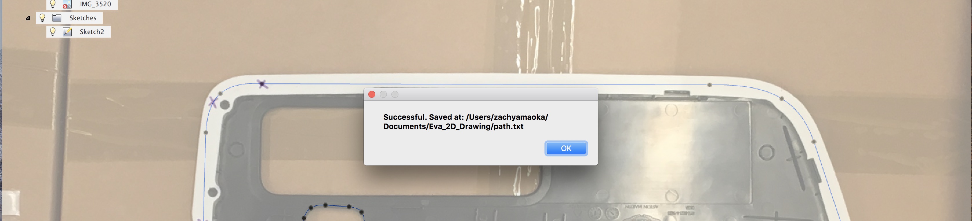
- Back in Fusion 360, select the EvaDrawPath script and press run!
- Connect to EVA over choreograph
11. Move the end effector to the desired starting position and orientation. When the code is run, it will keep this same recorded position but self correct the head orientation to point straight down.
12. From Choreograph navigate to Dashboard, then Go To, ensure lock is activated, click Fill Current. Record the joint angles

- Click on your user profile in the top right, then profile. Record the API key

14. Using your favourite text editor, open the file calc_tool_path.py. Edit code to enter in
the correct API key, the measured joint angles, and ip adress you used to connect:
host_ip = "http://172.16.16.2" # Ip you used to connect to choreograph
token = "cec3d52b-ad0c-4caf-8624-95f09381fce9" # API Tokens
start_joints_deg = [8.58,-21.02,-131.61,5.03,-27.68,-91.19] # Read from Go-to on choreograph
The code will use the joint positions to locate the Fusion 360 origin, and your drawing in real space.
15. Make sure the lock is off in choreograph. cd into the Eva_2D_Drawing directory,
from terminal activate the virtual pipenv (which should have been installed in this directory):
pipenv shell
If your getting errors, like ModuleNotFoundError: No module named 'automata',
it is because the environment has not been activated. Once activated, double check your still
in the Eva_2D_Drawing Directory, Place the e-stop next to you, then run from terminal:
python calc_tool_path.py
- It is unlikely that the robot will execute the path perfectly to begin with.
- If not going far enough, recalibrate image size in Fusion 360 and adjust drawing
- To calibrate image size, use measuring ruler between two known features the image, and then use that distance in real life.
- Tip: make a straight line tool path starting at one feature and ending at the other (of the two features you are measuring). Run the robot. Adjust the length/angle of the line in fusion, until EVA is going to the desired location in real life. Then recalibrate the image in Fusion so it matches.
- If going far enough but at wrong angle, adjust orientation of image in Fusion 360 and then adjust drawing.
- Remember to run Fusion 360 script again to export the new path data.
- contact @ zach.yamaoka@gmail.com if you have questions!